User's Manual for Practical Thermal History Sensors (Referthermo)
1.Concept of the Referthermo sensor
A Referthermo sensor is produced by molding alumina or other ceramic powders into a specified shape. When heated, this sensor undergoes shrinkage and densification, just like other ceramics, forming a dense body.
The JFCC Referthermo sensors are practical reference tools whose chemical composition, particle size distribution, molding density, etc. are rigorously controlled during production. Their shrinkage and densification represent highly reproducible phenomena according to the thermal history that varies depending on firing conditions, making them ideal for use as practical thermal history sensors.
When using for firing procedures, place the Referthermo sensors in a desired position inside the furnace. After firing, let them cool down to room temperature, then measure their dimensions using a micrometer (Fig. 1).
2.Chemical composition of Referthermo sensors
The following table lists the major components of Referthermo sensors.
| Component | Referthemo type | ||||
|---|---|---|---|---|---|
| H | M | L | L1 | L2 | |
| Al2O3 | >95 | >88 | -- | >50 | >50 |
| SiO2 | -- | <10 | >60 | >30 | >30 |
| MgO | -- | -- | <32 | -- | -- |
| CaO | -- | -- | < 5 | -- | -- |
| B2O3 | -- | -- | -- | < 8 | < 8 |
Note that Referthermo sensors also contains organic binders (PVA and PEG base) at weight concentrations of several percent.
3.Referthermo sensors and firing conditions
3-1. Referthermo sensors and thermal history
When a Referthermo sensor is placed inside a furnace, it may be subjected to three modes of heat transfer. (See Fig. 2.)
(1)Heat transfer by convection of environmental gas
(2)Heat transfer by radiation from heating element and components inside furnace
(3)Heat transfer by conduction through contact with kiln tools such as heat-resistant setters, etc.
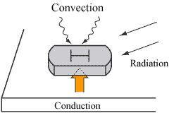
Figure 2. Three modes of heat transfer
The thermal history means the overall magnitude of three heat transfer modes to which this sensor is subjected.
3-2. Referthermo sensors and holding temperature
Within the operation temperature range, the degree of shrinkage of a Referthermo sensor is larger when held at a higher temperature.
For example, if a Type M sensor in the Referthermo series is held at 1,300°C and 1,500°C in air for two hours with other standard conditions described in 3-7, measured typical lengths after shrinkage are as follows.
| Example of shrinkage: Type M sensor | 21.05mm (at 1300°C) 18.51mm (at 1500°C) |
|---|
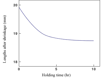
3-3. Referthermo sensors and holding time
The shrinkage of a Referthermo sensor is larger with longer holding times, even when fired at the same temperature.
For example, Fig. 3 shows the shrinkage behavior of a Type M sensor fired at 1,450°C with holding time.
3-4. Referthermo sensors and setting position inside the furnace
Since different temperature gradients will result from different positions inside the furnace, the shrinkage of a Referthermo sensor may vary depending on its setting position in the firing furnace.
Even for the same temperature setting, shrinkage will differ depending on the magnitude of each heat transfer mode at the setting position. For example, when some Referthermo sensors are placed in different positions at 1,500°C as monitored by the thermocouple, shrinkage of the sensor at the position where the convection of the environmental gas is stronger may be greater than that of others. In other words, thermal history at the position where shrinkage of the sensor is larger is more significant.
Therefore, it can be said that the Referthermo sensor is a practical thermal history sensor which indicates not just the temperature and time, but the degree of influence of heat transfer modes at the setting position, which manifests as the amount of shrinkage—i.e., the length after shrinkage. This can be used to determine the distribution of thermal history inside the furnace.
3-5. Referthermo sensors and the atmosphere inside the furnace
Referthermo sensors are intended for use in ambient air. Note the following precautions for use in neutral or reducing atmospheres or a vacuum.
First, components evaporating from Referthermo must not be allowed to adversely affect the furnace or products. Potential evaporating components include gases released by the decomposition of organic binders and carbon. *1 When the Referthermo is heated in a vacuum or in a low oxygen partial pressure environment, inorganic gases such as MgO, AlO, and SiO may be generated from the components of Referthermo sensors.
Secondary, a Referthermo sensor may indicate a magnitude of thermal history -i.e., the Referthermo index in below (6-1), far from the temperature setting. *2 In such cases, the Referthermo sensor functions as a thermal history sensor for the entire firing system that includes the effects of the atmosphere, including concentrations of oxygen or the other composition gas.
*1:For example, CO2, 1-propene, acetaldehyde, etc.
*2:The "Length-Referthermo index Conversion table" does not apply in this case.
3-6. Referthermo sensors and placement inside the furnace
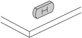
Depending on firing conditions, the Referthermo sensors may undergo warping, preventing accurate measurement of length. One condition that can lead to warping is heat transfer through convection and radiation that exceeds heat transfer via conduction from the setter (Fig. 4). This will cause the upper part of the Referthermo sensor to shrink more, resulting in warping in the upward direction.
Therefore, it is recommended to set the sensor on its side, as shown in Figure 5, to reduce warping deformation.
Warping deformation can be prevented through uniform heating of the entire Referthermo sensor. Carefully observe the sensors. Warping indicates that the products have also been subjected to an unbalanced heat supply during the firing process.
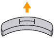
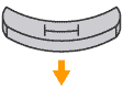
Figure 4. Relationship between heat transfer modes and warping deformation
3-7. Standard conditions for heat treatment for Referthermo sensor
The accuracy of evaluations of shrinkage properties is critical when using Referthermo sensors. As mentioned above, heat treatment conditions that can affect Referthermo shrinkage include the temperature program pattern (holding temperature, holding time, and rates of temperature increase/decrease), setting position inside the firing furnace, and the firing atmosphere. The standard conditions of heat treatment evaluation for Referthermo are as follows.
| Firing furnace | Batch electric furnace |
|---|---|
| Setting position | Soaking zone inside the furnace |
| Atomsphere | Air |
| Rate of temperature increase | 200°C/hour |
| Holding temperature | 2 Hours |
| Rate of temperature decrease | 300°C/hour |
If the above conditions are not met, the Referthermo index will sometimes not match the temperature obtained using a thermocouple. In addition, even if the sensor is fired under the above conditions, depending on the condition of the furnace and other factors, the Referthermo index may not always match the temperature obtained using a thermocouple.
3-8 Precautions for using Referthermo sensors
- Store Referthermo sensors in a cool, dark place as they may deteriorate under hot and humid environments.
- If there are burrs on the surface to be measured as remnants of the molding process, wipe them off with a soft cloth before placing inside the furnace. After removing from the furnace, allow the sensor to cool to room temperature before measuring. Remove any adhering materials on the surface to be measured. This will allow for more accurate measurements.
- Wherever possible, set the Referthermo sensor on its side, to prevent warping deformation.
- Always set the Referthermo sensor at the same position in the furnace. (This will reduce the discrepancies attributable to location.)
- Before using a Referthermo sensor in an atmosphere other than ambient air, please test beforehand for any effects, as any atmosphere different from air may affect the product or other components. When firing high-purity products, even in ambient air, test before use to rule out the risk of contamination by gases released from decomposition of organic binders.
- Each Referthermo sensor type has a different composition. Positioning them next to each other during firing may result in mutual interference. For example, it has been confirmed that placing Types H and M, Types L and L1, and Types L1 and L2 next to each other during firing in ambient air will result in inaccuracies in the Referthermo index obtained due to mutual interference.
- Before measurement, let the Referthermo sensor stand at room temperature for at least one hour. When measuring the length of the Referthermo sensor, be sure to use a micrometer, not a digital caliper.
*We are not responsible for malfunctions or accidents caused by failure to observe the above precautions.
4.Features, method of use, and responses to abnormal values of Referthermo sensors
Firing process control generally involves maintaining a steady state inside a furnace by monitoring the temperature inside the furnace with thermocouples or infrared radiation thermometers. However, it is well known that methods based on temperature sensors are insufficient for monitoring important factors other than temperature. And the measuring instruments themselves are difficult to calibrate.
Seger cones or Orton cones similar to Referthermo sensors have been used in the past. However, the firing procedure conditions cannot be quantified using these cones, because these cones have oblique square pyramid shapes and rely on melting that bends the narrow tip.
Referthermo sensors use the shrinking phenomenon; thermal history is expressed numerically, improving detection sensitivity for abnormalities. Use with control charts and other process control methods enhances detection sensitivity for abnormalities.
Referthermo sensors aren’t mere temperature sensors; they are thermal history sensors. Any anomalies in the overall thermal history are observable as anomalies in the manner of shrinkage. These shrinkage anomalies may be attributable to changes in the conditions listed above in "3. Referthermo sensors and firing conditions." You will need to undertake a confirmation experiment. Since the Referthermo sensor is a thermal history indicator, it can accurately detect abnormalities in thermal history based on the assumption that relevant temperature control is properly performed.
Examples of applications
- Thermal history distribution in a furnace (thermal history differences due to position in furnace)
- Confirmation of interference differences (detection of differences among furnaces of the same model and between furnaces of different models)
- Influence of and differences of occupied volume in furnace (detection of difference due to the amount of product to be fired)
- Prototyping (detection and confirmation of differences for each step during the transition from experiment to trial production to mass production)
- Differences in heat transfer modes depending on heating source
- Daily management of furnace and firing process, monitoring of changes over time, early detection of abnormalities
- Assessment of the outsourced processes (having Referthermo sensors fired together with the product, and confirming by checking its length upon acceptance)
- Quality control (firing together with the product and utilizing the results for x-R control chart, etc.)
- Assessment of the daily firing conditions of continuous furnaces, tunnel furnaces, etc., and standardization of the firing process
5.Quality assurance philosophy of Referthermo sensors
Calibration of the furnace and the verification of thermocouples are not sufficient for ensuring that the same thermal history to which the products are subjected are being maintained. In other words, one can institute the most rigorous temperature controls and still fail to reproduce the thermal history perfectly. This is precisely why the Referthermo sensor was developed as a practical reference tool.
To maintain functional accuracy in evaluations of the properties of Referthermo practical reference tools, huge reference pieces were selected for each Referthermo type and have been stored as master lots under the most suitable conditions. Then, the length of the sensor in the master lot with respect to the holding temperature was measured using a controlled and calibrated furnace and thermocouples. The firing process of the sensor in the master lot was repeated using finely controlled conditions to produce the master curve showing the relationship between holding temperature and lengths after shrinkage.
Each new lot of the Referthermo sensors must be fired with a sensor from the master lot at 50°C intervals; the shrinkage of the new lot is compared and adjusted to the master carve. This makes it possible to continue supplying Referthermo sensors with properties virtually identical to the master lot on a near-permanent basis.
6.Operation temperature range, and measuring repeatability of the Referthermo index
6-1 Referthermo Index
Referthermo sensors employ an index named the Referthermo index, a value similar to the temperature that the Seger cone deformity after firing indicates. The Referthermo index represents the overall thermal history and does not indicate actual physical temperature.
For example, if Type H sensors are heated with sensors from the master lot under the specified firing conditions above (3-7) at a holding temperature of 1,600°C, the typical lengths will be around 20.50 mm. If we repeat the firing conditions evaluation in the range from 1,400°C to 1,700°C in a similar manner, we will be able to create a table showing the relationship between holding temperature and length. However, since the temperature setting may not always represent the thermal history, the holding temperatures in this table must be values derived from the master curve mentioned in (5) together with the lengths of the co-fired master lot sensor. They are called “indicated temperatures” and are not actual temperature settings. The Indicated temperature corresponding to the measured length in the above table is called the Referthermo index, which is expressed as a dimensionless value—for example, "RT-1600." The "RT" stands for Referthermo, and the "1600" stands for the Indicated temperature (°C).
6-2 Operation temperature range and measuring repeatability of Referthermo index
| Referthermo type | Operation temperature range | Measuring repeatability of Referthermo index |
|---|---|---|
| H | 1400~1700℃ | ±10℃ |
| M | 1200~1500℃ | ±10℃ |
| L | 1050~1300℃ | ±10℃ |
| L1 | 800~1150℃ | ±15℃ |
| L2 | 600~900℃ | ±15℃ |
7.How to Select the Optimal Referthermo Type for Your Needs
Guidelines for the operation temperature range of the Referthermo sensors is provided above (6-2). Nevertheless, you should not base your decision on the operating temperature alone.
If your product is intended to be kept in air for two hours, the sensor can be selected in accordance with the guidelines provided. For example, if the firing temperature is 1,350°C, select Type M sensor; if the temperature is 1,150°C, then select Type L sensor. For firing at 1,250°C, try both Types M and L under actual firing conditions, then select the type whose length plots are closer to the center in the conversion table.
Next, we will discuss the case for different holding times in air. If the holding time exceeds two hours, you should shift your choice to the higher temperature types, and if it is shorter than two hours, shift to the lower temperature types. For example, if the firing conditions are 1,250°C for 30 minutes, then Type L sensor may be more suitable than Type M sensor.
If the atmosphere is not ambient air, you must select probable suitable type based on the temperature and holding time, then confirm the selection based on the actual testing results under those conditions.
8.Typical relationship between length after shrinkage and Referthemo index (graph)
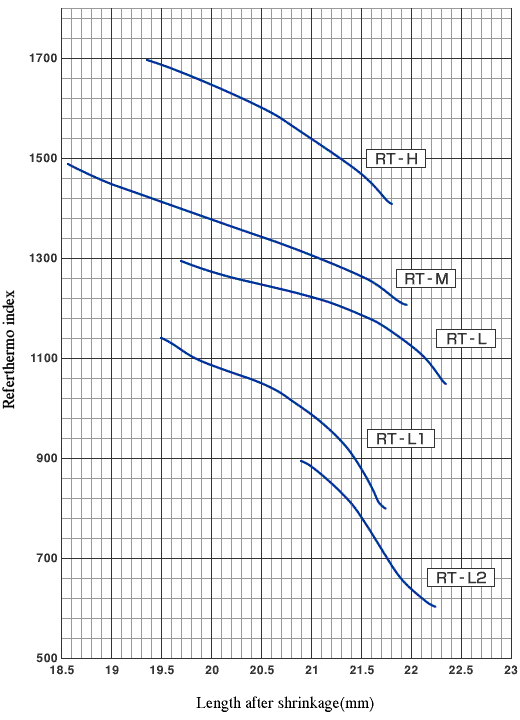
* For actual relationships, please be sure to refer to the “Length-Referthermo index Conversion table” enclosed with the product.